We have recently published two new papers in the Journal of Experimental Biology detailing the results of field experiments we carried out. Our goal was to monitor the behavior and internal temperatures of sea mussels (Mytilus californianus) on the shoreline, and link their recent experiences to their physiological status. There can be substantial variation in the environmental experience of mussels sitting only a few centimeters away from each other, and this project was an attempt to catalog that variation for the first time in a wave-swept rocky intertidal environment. This project involved the development of a new datalogger system (MusselTracker) to allow us to attach individual sensors to live mussels and deploy them in the field for multiple weeks on battery power. The MusselTracker system is described in our papers, and on my GitHub site: https://github.com/millerlp/MusselTracker which also includes the design files and software to recreate the system. The two papers are:
Miller, L.P. and W.W. Dowd (2017). Multimodal in situ datalogging quantifies inter-individual variation in thermal experience and persistent origin effects on gaping behavior among intertidal mussels (Mytilus californianus). Journal of Experimental Biologyhttp://dx.doi.org/10.1242/jeb.164020
Gleason, L.U., L.P. Miller, J.R. Winnikoff, G.N. Somero, P.H. Yancey, D. Bratz, and W.W. Dowd (2017). Thermal history and gape of individual Mytilus californianus correlate with oxidative damage and thermoprotective osmolytes. Journal of Experimental Biology http://dx.doi.org/10.1242/jeb.168450
To accompany that information, here I outline the process of making the actual wired sensors that we attached to the mussel shell.
Valve gape sensor (red), 3-D orientation sensor (yellow), and thermocouple temperature sensor (small black wire) mounted on a live Mytilus californianus mussel.
Here’s a pictorial walkthrough of the process I used to waterproof our accelerometer and hall effect sensors for our mussel tracking experiment.
The goal was to stick 30 of these little breakout sensor boards on the end of cables, and run the cable back through a waterproof bulkhead fitting into a waterproof box that housed a datalogger.
Reflow-soldered hall effect sensor boards.
For cabling we settled on standard USB cable since we needed pieces that were between 12 and 24″ long. Cutting up 6′ long USB cables worked fine for this purpose. Monoprice.com has some of the cheapest prices on USB cables. The diameter of the cable will vary with the length of the cable and the application. These 6′ micro-USB cables have an outside diameter of about 3.9mm (0.15″), and have 4 28-gauge conductors (typically red, black, white, and green) along with a foil shield, a copper drain wire, and additional shielding wire outside the foil. For less than $2 a piece, they’re quite well made. There are smaller diameter cables available in shorter lengths, but cables that are longer than 6′ (1.8m) are usually made of larger diameter wire, around 0.2″ or larger.
A micro-USB cable ready to be sacrificed.
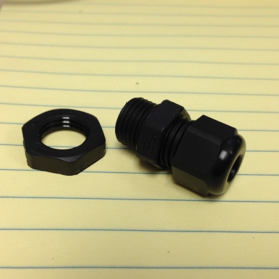
The first step is to install the bulkhead fitting so that you don’t forget it later.
Bulkhead fitting from McMaster-Carr.
The bulkhead fittings we used were obtained from McMaster.com, and are referred to generically as nylon liquid-tight cord grips. These are made for 0.08 – 0.2″ diameter cable, part number 69915K46. They have a PG-7 thread on the base, which is essentially a 1/2″-20 UNF thread, but is not tapered and won’t be self-sealing like a tapered pipe thread. Larger versions of these fittings are available with tapered pipe threads. The fitting does come with an o-ring that seals against the flange in the middle of the body when screwed into your bulkhead, but we back this up by gluing them in place whenever possible.
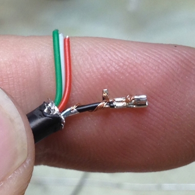
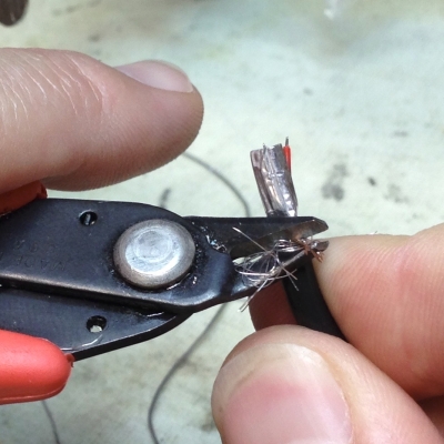
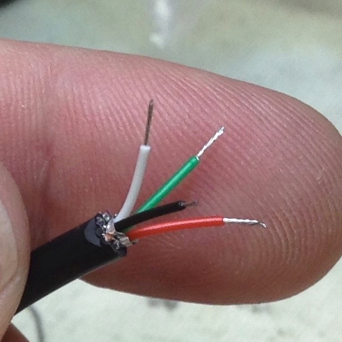
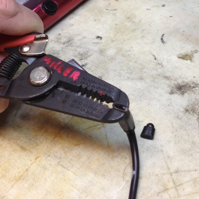
Put the bulkhead fitting on before installing the ends on the cable. You may be able to see the marking on the USB cable that says 28AWG/1P + 28AWG/2C. This apparently translates into 28-gauge 1 pair conductors (the data lines), and 28-gauge, 2-conductor (the power and ground lines). Larger cables will often have 24AWG/2C for the power lines to help with higher USB charging currents, and 28AWG/1P for the normal data lines.Strip the outer jacketing.This reveals the shielding wires and foil. One of the wires will be the copper drain wire.Cut away all the shielding wire and the foil shield, leaving the 4 colored wires and the copper drain wire.
Strip a few mm of insulation off the end of the black wire, which we’ll use for ground.Wrap the drain wire around the ground wire, and twist the two together at the end. Because the other end of this cable will not be grounded, I attach the drain wire to ground at this end so that the shielding can do its job.
A person with a lesser sense of humor would title the next section something like “Crimpin’ ain’t easy”, but this is a classy website, so I won’t do that.
For the cable to datalogger connection, we use JST PH-series connectors. A 1×4 male header is installed on the datalogger board, and the cable will get a matching 1×4 female connector. This connector is narrow enough to fit through the large hole you have to drill in the box for the bulkhead fitting. The crimp-on female ends are JST part number SPH-002T-P0.5S. They insert into the 1×4 plastic housing part number PHR-4.
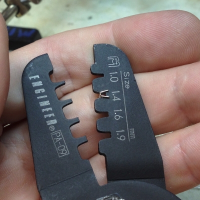
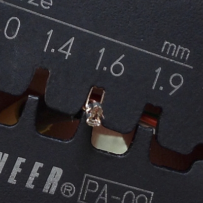
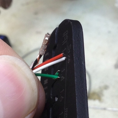
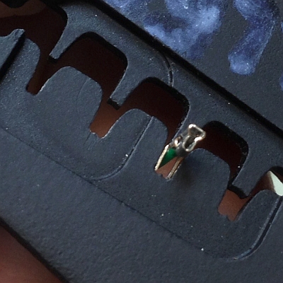
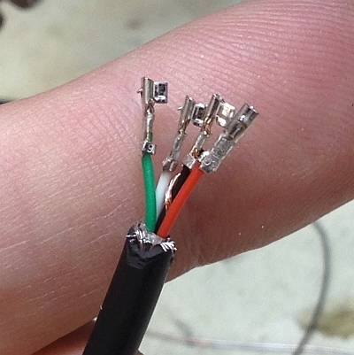
JST PH series crimp-on female ends.The process I’ve worked out is to first put the crimp pin into the crimping pliers so it is wedged in place.These crimping pliers are found on Amazon and other retailers usually labeled something like Engineer PA-09. I crimp the wire leads in the 1.4mm opening, and the cable strain relief in the 1.6mm opening afterwards.The wire gets inserted into the crimp pin so that the jacketing is roughly even with the taller strain relief wings that are still visible here, sticking out of the pliers. The bared wires are sticking into the area where the crimpers will crush the crimp pin around them.This is the partially-crimped connector. The bared wires of the black wire are crimped into the pin, and the tall strain-relief wings of the pin are still un-crimped. The bared wires of this particular cable were slightly longer than necessary.Here you see the crimp pin from the other end, mounted in the 1.6mm opening so that the tall strain relief wings are ready to be crushed around the black jacketing of the wire.Here’s the completed strain relief crimp, which grabs the insulation of the wire without fully crushing and severing it.Then it’s time to strip a bit of the other wires and crimp the pins onto them. Once again I start with crimping the bared tip of the wire, leaving the strain relief untouched.Now with the strain relief tabs mounted in the 1.6mm jaw after the wire connection is crimped.And a slightly blurry picture of midway through the crimping movement. Notice how the shape of the crimp jaws has caused the strain relief tabs to curl in on themselves. Ideally the curve will continue so that the curves end up pressing against the cable jacketing, rather than the sharp ends of the wings cutting the jacketing and wire. Always buy extra crimp pins, since you’ll have a few of these go bad, especially as you’re starting out.4 completed crimps.Each crimp pin gets inserted into the JST connector housing, in the correct orientation and order. There is a little tab on the crimp pin that will catch the plastic tab of the connector housing.All four pins inserted fully into the connector housing.
That concludes the proximal end of the sensor cable. The remainder of the work involves installing the sensor board and waterproofing it.
Add some heat shrink onto the other end of the cable before installing the sensor board.Strip off the outer jacketing on this end.Fold away the shielding wires so I can trim them off.Clip all of the shielding wires off, along with the copper drain wire on this end, since we already connected the drain wire at the other end of the wire. The foil shielding also gets removed to reveal the 4 wires.Strip off a few mm of all 4 wires, and tin the ends with solder so that they don’t splay open when inserting them through the sensor board holes.On the sensor boards I placed four small holes for the wires to mount to. The order matters here so that the correct voltage and signals are coming and going to the correct terminals.This bit is fiddly, but eventually I get all 4 wires inserted into the holes, in the correct orientation.At this point it is time to solder the wires to the holes on the sensor board.The four wires soldered into place, hopefully with no solder bridges between wires.
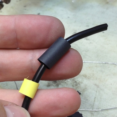
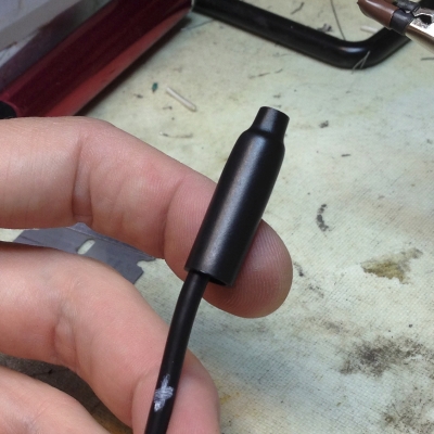
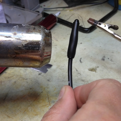
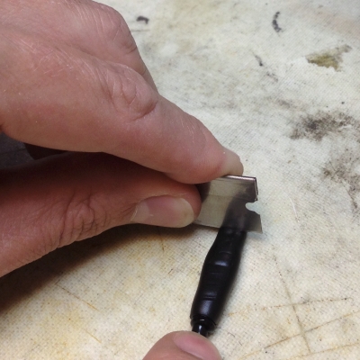
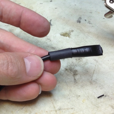
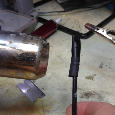
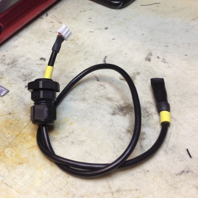
Trim off the excess, since the goal is to have as small a sensor as possible.Carefully bend the wires so that the sensor board is sticking out parallel with the main cable.An accelerometer board with the wires soldered in place. Notice there are some bare strands visible, so you have to take care that they don’t touch each other.Start adding heat shrink. To start with I cut a piece of thin wall adhesive-lined heat shrink. This came from McMaster-Carr, part number 7861K53.Shrink the tubing over the sensor board and the exposed wires, making sure to catch a bit of the main cable jacketing as well. This heat shrink is lined with an adhesive that will melt and flow a bit around the parts on the board, helping prevent the ingress of water.Once the heat shrink is shrunk, I use a pair of pliers to smoosh the free end of the hot tubing flat, so that the adhesive sticks the two sides together.The flattened end of the adhesive-lined heat shrink tubing. This is somewhat waterproof on its own, but isn’t particularly robust in the face of breaking waves.The real secret sauce is these heavy duty heat shrink end caps, also from McMaster-Carr. I tried two sizes, 0.25″ initial diameter (part number 72855K23), and 0.38″ initial diameter (part number 72855K24). They both end up about the same length when shrunk (0.6-0.72″), and both shrink to around 0.08-0.09″ inside diameter. The larger diameter pieces were easier to use with these sensor boards, which were a bit more than 0.25″ wide after the first layer of heat shrink was applied.Drop it over the end of the sensor. The heat shrink cap should be long enough that it will shrink around the black jacketing of the cable, sealing up everything inside of it. These end caps also have an adhesive lining that melts around the pieces inside.The caps are very thick compared to normal heat shrink tubing, so they take a long time to heat to shrink. It is possible to overheat them so much that the solder on the boards starts to loosen and chips move around inside, so I go slow on the lower-heat setting of the heat gun.Like the first layer of heat shrink, I use pliers to smash the end of the cap flat while it is still hot and flexible.Smashing it tends to leave a lot of extra material beyond the end of the sensor board. While things are still hot I trim it with a razor blade.Follow that up by using the pliers to crush the end again while still hot. You can see the melting layer inside, and you want to make sure this is smashed flat so it adheres and forms a watertight seal.Remember that extra piece of heat shrink we slipped on the cable a while back? I now bring this up and use it as an extra layer of sealing for the flexible wire and the relatively stiff joint that forms where the end caps melts around the wire. This is more adhesive-lined heat shrink.More fun with the heat gun.Finally, there was that piece of yellow heat shrink I slipped on earlier. This is just there so I can color code different sensors, and it gives a convenient place to write information with a Sharpie marker. The colored heat shrink is not adhesive-lined, so I only use it for marking purposes. It can’t be trusted to stay sealed when submerged in water.There’s the completed sensor lead. It is possible to pull the crimp pins back out of the 1×4 connector housing and slip the wire out of the bulkhead fitting, but we assembled them this way so that the whole assembly could be inserted into the box through the bulkhead fitting hole and glued in place. Superglue (cyanoacrylate) sticks very well to the heat shrink end caps when they need to be attached to the study subject.
Thermocouples. We also had thermocouple sensors on this project to measure temperature, which were built with 36-gauge K-type wire from Omega, with a PFA (Teflon-like) jacketing. To toughen these up, we covered them with 1/32″ heat shrink tubing, which increases the diameter of the lead, but makes them more resistant to abrasion.
A 36-gauge thermocouple lead jacketed with 1/32″ heat shrink tubing.
The tips were twisted together with forceps and soldered to form the temperature-sensing junction that would be inserted in the mussel.
The soldered tip of the thermocouple.
It’s very important to note that seawater can migrate up the wires of the thermocouple, inside the jacketing of the individual wires, and make its way into a watertight box. To combat this, you must coat the tip in something, whether that is adhesive-lined heat shrink, superglue, silicone, or polyurethane, in order to waterproof the tip.
To get these small thermocouple leads into our waterproof box, we used a 4-hole liquid-tight cord grip from McMaster, part number 7807K32, for 4 cords of 0.05-0.06″ diameter. The 1/32″ heat shrink makes the size of the thermocouple lead large enough to be snugly gripped by this bulkhead fitting.
Testing
That pile of breakout boards shown at the top of the post presented plenty of opportunities for bad solder joints to cause problems. During the assembly process for each sensor, I built a test rig on a breadboard that allowed me to test each individual breakout board with a simple pass-fail indication.
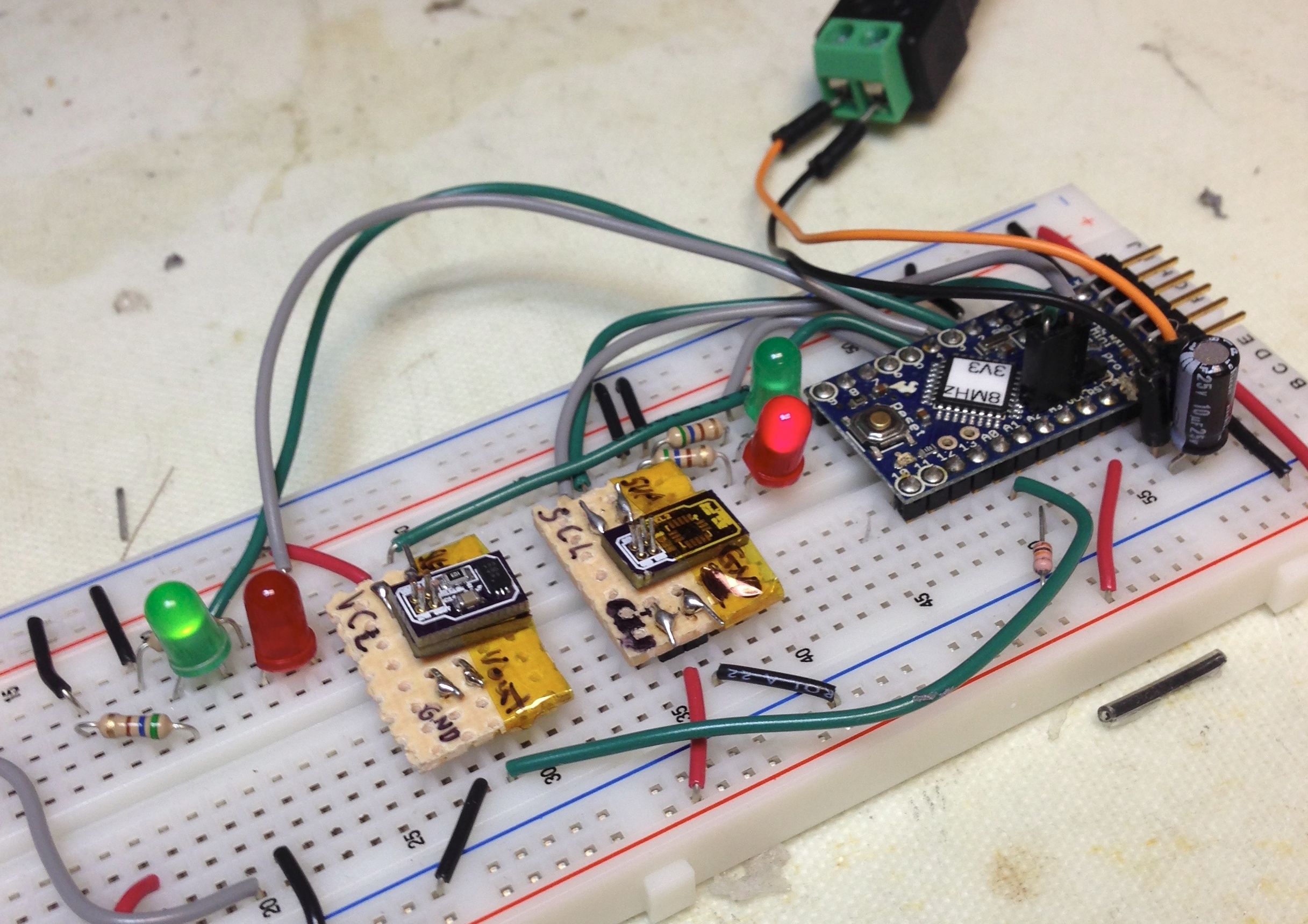
The testing rig.
The board is run by an Arduino Pro Mini 3.3V board loaded with a simple program to test the hall effect sensor or the accelerometer/magnetometer sensor boards. The mounts for the two different boards are seen to the left of the Arduino, and they have little wires sticking up through the 4 holes where the sensor board sits. I could then simply slide the sensor board onto the 4 leads, and power up the Arduino. The Arduino would attempt to talk to both the the hall effect sensor and the accelerometer, and if it got reasonable responses it would turn the green LED on. If it didn’t get a response, it turned on the red LED. A set of pogo pins would have made this easier to slap the sensor boards onto, compared to the 4 wires sticking up, but this was a short-term project that didn’t warrant making a whole special testing PCB design.
The hall effect sensor board on the left passes (green light) while the unused accelerometer tester on the right fails (red light).