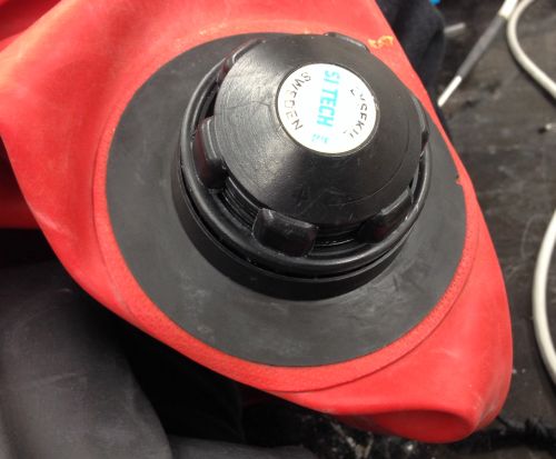
Experienced cold water scuba divers will tell you that a dry suit is a vital piece of safety equipment, especially in challenging conditions (seriously, they’ll tell you without prompting, and then babble on about their gear until you walk away). Serious divers will also tell you that maintaining your gear in tip-top shape is an important safety issue, and all service should be done by trained technicians (again, it’s like that old joke: How do you know someone is vegan/went to Princeton/is from California? Answer: They’ll tell you. Divers, particularly overweight men with walrus mustaches, are the same way when dispensing advice about dive gear). Despite these undeniable truisms, I dive an old Viking suit that I bought off ebay and was probably manufactured in the late 80’s or early 90’s, and I do most of my own repairs despite zero training as a dive gear technician.
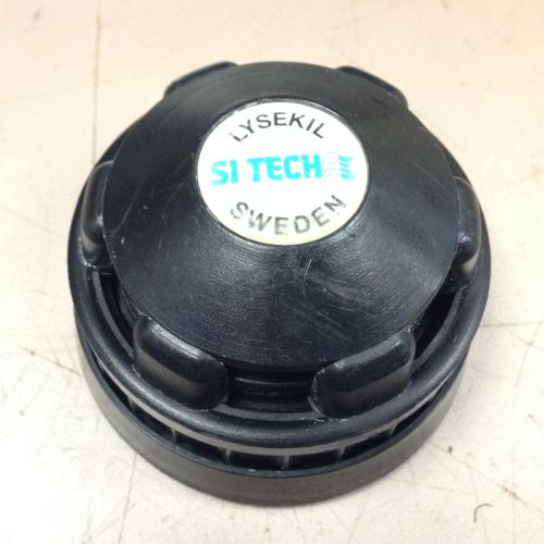
The disintegrating foam from my drysuit undergarment had apparently clogged up my dump valve, so it was letting water in. The obvious solution to this, for a 25+ year old suit with original valves, is to buy a replacement valve. The alternate solution is to crack the valve apart and try to clean it out. Here’s how that went:
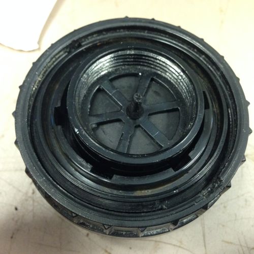
On the inside of the drysuit, there is a pronged plastic piece that threads into the outer valve body. I used a screwdriver for leverage to unscrew this piece.
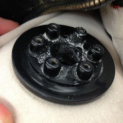
The attachment nut holds a large plastic washer (more of a backing plate really) against the inside of the suit body.
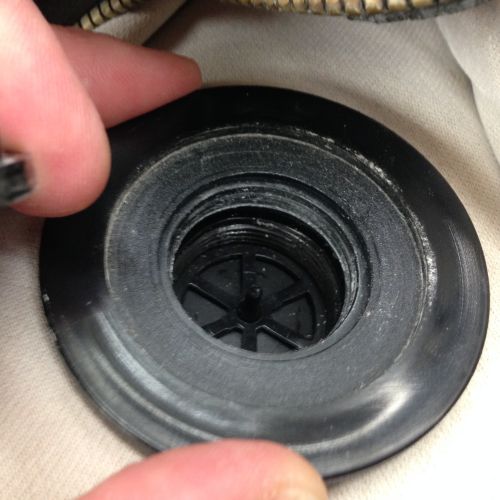
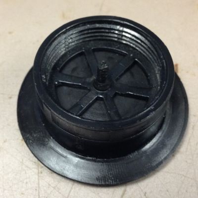
The outside of the valve then drops off the suit, revealing a crusty old rubber mounting gasket glued to the suit.
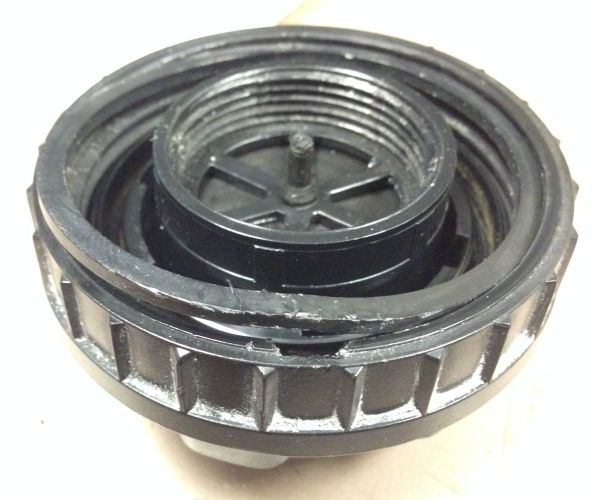
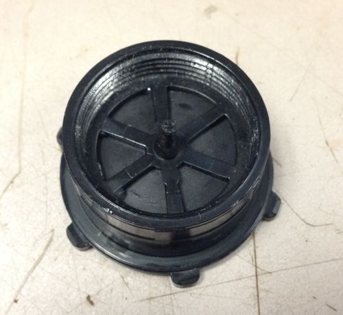
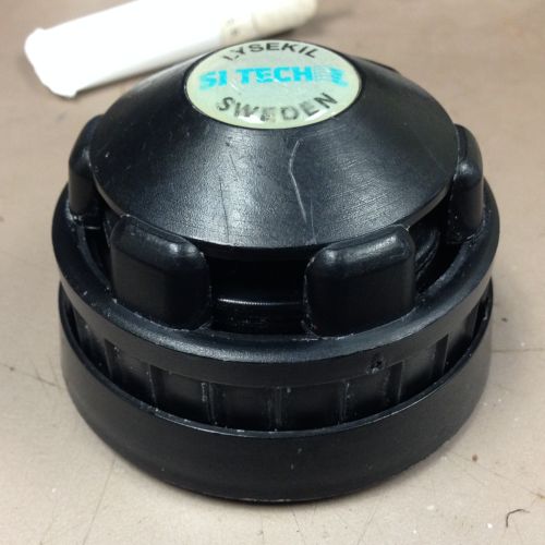
At this point you have the outer valve body sitting on the desk, and there aren’t any more handy screws to help take it apart further.
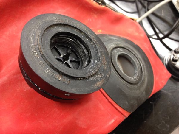
My best guess was that it snaps together somehow, so unsnapping it turned out to be a matter of pulling and prying until the main rotating body of the valve popped loose from the base (the “protector ring” in Si-Tech parlance). Popping the rotating body off leaves you with the body, a large spring, and the protector ring.

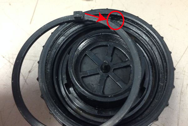
The next step wasn’t terribly obvious either. I tried screwing and unscrewing and probing with a screwdriver, and couldn’t do much. You can unscrew the inner rotating portion of the valve to a certain point, but it hits a stop. What you have to do is remove what I’ll call the retaining ring from the valve body, somehow without cracking the ring. In the image below, you’ll see a small gap circled in the rim of the main valve cap, and the retaining ring sitting inside/below that rim. I wedged a small screwdriver in that gap between the valve cap and the ring, and pried it up.
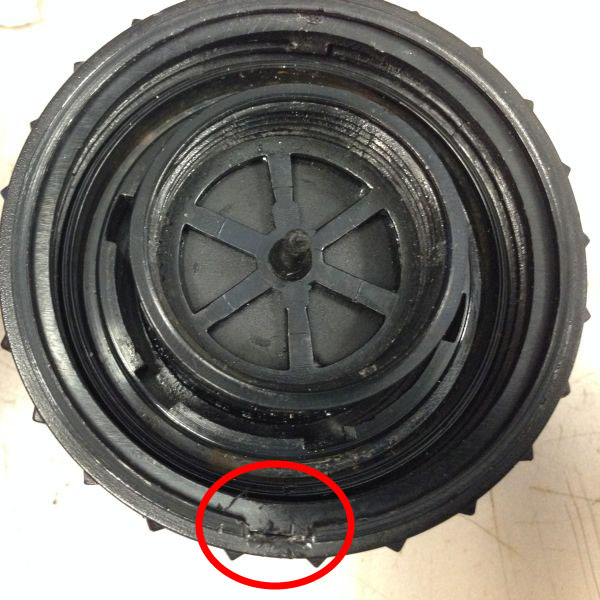
This move was probably the riskiest part of the process, because if the 25 year old plastic retaining ring snapped, I was going to have to buy a whole new exhaust valve.
With the retaining ring out, it was then possible to unscrew the threaded insert that holds that central guide sleeve, membranes, and the piston + small spring in place inside the valve body cap.
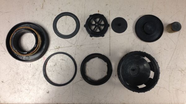
In the layout above, ignoring the protector ring on the far left, the bottom row (L to R) consists of the retaining ring, the threaded insert, and the valve body cap. The top row consists of a thin rubber membrane that mounts on the guide body next to it, and a rubber valve that mounts inside the guide body, followed by the piston and small spring.
The pieces that needed cleaning were the two rubber pieces that mount on the guide body. I wiped these down, and reapplied silicone grease to help keep the rubber bits moving smoothly.
Reassembly is the reverse of disassembly. Drop the small spring and piston back into the valve body cap.

Follow the piston with the guide sleeve, which simply drops in on top of the piston. Then follow with the threaded insert that screws in to the valve cap body, and traps the guide sleeve and piston inside the valve cap body.
Reinstalling the retaining ring involves one hopefully obvious step. You must align the tang in the retaining ring with the slot in the valve body cap. The tang is the part that stops you unscrewing the cap too far. It’s not like the retaining ring will really fit in any other way, but you might as well not screw it up. The picture below shows the retaining ring flipped over to reveal the tang, which normally sticks down into the valve cap as it sits in the picture.
With the retaining ring reinstalled, the next step is to put the big spring back into its resting place, and snap the valve cap back onto the protector ring (base). To do this, you need to make sure the 6 tangs on the protector ring line up with the 6 slots in the guide sleeve as you cram the two pieces back together.

With the two parts successfully snapped back together, you should be able to tighten and loosen the valve body cap like it used to work, and it should hit the stop when you try to unscrew it too far. I had to use a fair amount of pressure to get the two pieces to snap back together fully, so don’t be afraid to lean on it.
After you have a reassembled outer valve body, it’s just a matter of refitting it to the gasket on the drysuit, and replacing the inner backing plate and attachment nut to securely fasten the valve to the suit.
Hopefully that’s $60 saved by not having to buy a new dump valve. My comfort and safety are not worth $60 at this stage.