
Design files and code for this project can be found here: https://github.com/millerlp/Time_lapse_arducam
The goal of this project was to build a cheap and power-efficient time lapse camera to monitor some of my experiments in the field. The camera would capture an JPEG image every 30 seconds and write it to a micro SD card, and be able to run off of AA batteries for a day or two at least. To accomplish this, I build an Arduino-like controller board that would interface with an ArduCAM camera module.
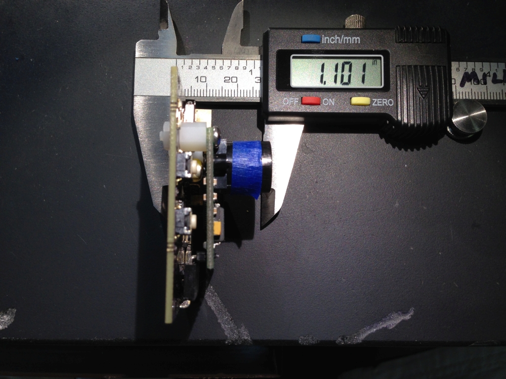
The ArduCAM module is a small web-cam style device that can be interfaced with microcontrollers such as the Arduino Uno. The ArduCAM is available in several resolutions, including the 2 megapixel (1600×1200) unit I used here, which cost about $30.
The primary issue with the ArduCAM (or really any camera module) is that it draws well over 100mA while running, since the sensor is powered on and updating the image constantly even if you’re not capturing an image at that moment. If you’re only taking a picture a few times a minute, this high power consumption just wastes battery. My board is designed to cut off all of the power to the ArduCAM module completely between image captures, so that the overall current draw of the board drops to less than 1 mA while sleeping between pictures.

The board consists of
- An ATmega 328P microcontroller, the same unit used on an Arduino Uno. It is set to run off of its internal 8MHz oscillator, mostly to reduce the parts count and simplify the board.
- Running the microcontroller without an external crystal also allows the use of a DS3231M real time clock module to control when the ATmega wakes (the 32kHz signal from the clock is attached to XTAL1 on the ATmega, so that TIMER2 can be used to wake the ATmega once per second). The real time clock is also used to keep the date and time so that the captured images can have that information embedded in the file.
- There is a micro SD card slot for storing the images.
- Two buttons are provided, one for reset, and one for a user-defined purpose. There are identical button footprints on the backside of the board in case that position is more useful.
- There are red and green indicator LEDs in the upper left corner, also with matching footprints on the back side of the board that can be used instead of the front positions.
- A 6-pin FTDI header in the upper right is used for uploading new firmware.
- A CR2012 backup battery keeps the real time clock running even if the main battery supply dies.
- There are several different power connector options, including two different locations for a standard 2.1mm barrel jack connector (pictured on the right side of the board) and a front or back location for a JST PH-series connector (as found on many lithium battery packs), visible near the top center of the board above.
- A 3.3V low-dropout voltage regulator provides power.
- A transistor (labeled NPN on the board) is used to cut off power to the ArduCAM module that mounts to the 8-pin right-angle header at the bottom of the board.
- The full parts list is available in the Excel file on the Github repository: Excel file
- If you want to order a copy of the circuit board (3 copies actually), you can go to OshPark.com:

- This board should also work with the 5 megapixel version of the ArduCAM since the pinout and command structure is the same.
The camera is made to fit inside a waterproof storage box as a fairly cheap, simple, weatherproof housing ($15). If you’re old, you know this as an “Otterbox”, but Otterbox hasn’t officially made waterproof boxes for several years now, since the smartphone case market was much more lucrative. The new brand name for Otterboxes is S3, but they are the same molds as the previous Otterbox. In my case, I used a T2000 model.

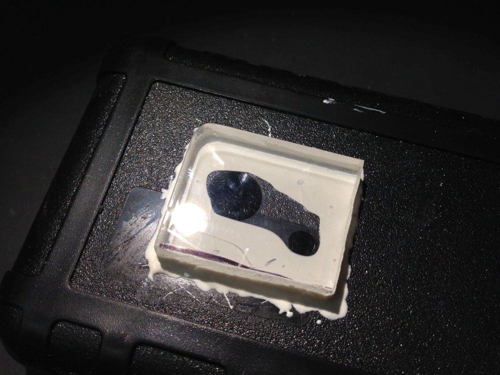
To see out of the box, it’s just a matter of drilling a hole for the lens port (there are clear versions of the S3 T2000 case, but the plastic of the case is too textured to serve as a lens by itself). A Unibit makes short work of this.

I also drilled a hole off to the side of the main lens hole to make the indicator LEDs visible when the box is closed. To make the box weathertight again, I cut out a piece of acrylic big enough to cover both holes.

I follow that up by using some 2-part marine epoxy to seal the acrylic piece onto the box, allowing it to dry overnight.
I used some 1-inch long #4-40 screws to create standoffs for the camera to keep it standing straight inside the housing. I add a bit of soft foam behind the camera when I close the lid to keep anything from rattling around. The 4-AA battery back sits next to it, and also gets wedged into place with some soft foam when the lid is closed.

On a set of 4 rechargeable NiMH AA batteries, the camera will take roughly 3600-4000 pictures.
Notes on the ArduCAM usage:
- The power draw of the ArduCAM while powered on is normally above 100 mA (mine is roughly 120 mA). There is a “low” power option that can be set in the ArduCAM controller, but this still leaves the power consumption well above 20mA.
- Completely powering off the ArduCAM like I do here causes it to lose any settings you might have made. It also creates the need for the camera module to go through its auto-exposure process when it restarts. If you try to capture an image too quickly after reboot, it may be radically underexposed or overexposed. In testing, I found that the ArduCAM needs roughly 3 seconds to get its auto-exposure set correctly, so my program pauses that length of time after rebooting the ArduCAM before capturing an image.
- I have one ArduCAM module that doesn’t always complete the setup loop in my program when the ATmega is first rebooted after the battery is connected. My program gives a series of flashes on the green LED to indicate that the board is resetting, then flashes when the ArduCAM is successfully recognized, and finally flashes again when the SD card is successfully initialized. On my flaky ArduCAM, I have to carefully watch for this series of flashes, and if it hangs after the 1st or 2nd flash, I hit the reset button on my board to restart the process. Once the full set of success flashes happens, the board will run for days without problems.
- I set the unit to take one image every 30 seconds. The default filenaming scheme will name the file using the year-month-day hour:minute:second, and also set those values in the file attributes.
If you’re building one of these boards from scratch, you will have to burn a bootloader onto the ATmega 328P after you get it mounted on the board. The board has a 2×3 header space on the board for use as a ISP programming header (it also has a footprint for a Tag-Connect TC2030-IDC-NL cable to do the bootloader programming, as that is what I often use instead of installing a full 2×3 pin header for this one-time function). You can use another Arduino as your in-system programmer, or a dedicated programmer like the USBtinyISP to burn the boatloader. Because the board uses a slightly different hardware setup compared to a normal Arduino Uno, you need to burn an appropriate bootloader. I have provided a modified entry for the boards.txt file that will specify which bootloader to use on this time lapse camera board. The new entry can be found at the Github repository: boards.txt entry. That entry should by copied and pasted into the default Arduino boards.txt file that is found in the /hardware/arduino/avr folder. On a Mac you would need to go to the Applications folder, command-click on the Arduino.app icon, and choose “Show package contents”. Then navigate to Contents/Java/hardware/arduino/avr to find the boards.txt file.
After the bootloader is installed, you can use a FTDI adapter to load programs onto the board. If you have a 5 volt FTDI adapter instead of a 3.3V version, you should probably remove the SD card for safety. All of the other parts on the board should be 5V tolerant.
Using the time lapse camera
I have a need to keep an eye on field experiments that I have running out on the wave-swept seashore, hence the need for a self-contained, watertight camera system. I bolt a mounting plate to the rock and attach the housing with stainless steel band clamps.

Here the housing will get splashed and submerged occasionally by larger waves at high tide, but it doesn’t end up submerged in deep water for any length of time. I wouldn’t necessarily trust my modified box to withstand the rigors of deeper underwater work, but it is fine for tidepool usage.
If you record long enough, you’ll eventually catch something weird, like this ground squirrel that appears to be munching on a mussel that it cracked open.
