A few years back I put together an electronic BBQ temperature controller that regulated the air temperature in my smoker and displayed the air + meat temperatures on a computer in my kitchen, while also posting the temperatures to Twitter. More recently I have decided that setting up my old desktop computer on my kitchen counter is a poor use of space, so I set about making a more compact temperature monitor.
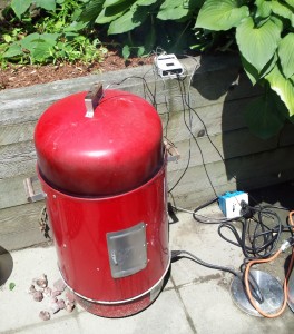
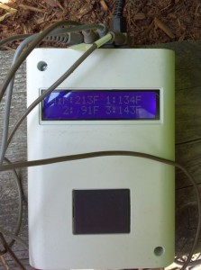
This time around the contraption is based on an Arduino board. It consists of a LCD to display air temperature and three additional meat temperatures, and a WiFi shield that acts as a little server on my home network so that I can check temperatures on my phone without getting up from the couch. The WiFi feature has replaced the Twitter feature of the earlier controller. The controller is hooked up to a Brinkmann “Gourmet” Electric Smoker, pictured at left.
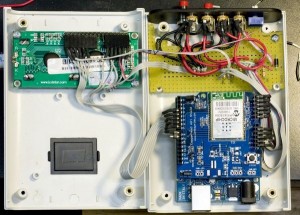
The whole thing consists of the following parts:
Arduino Uno ~$27
Link Sprite CuHead WiFi shield ~ $55
16×2 LCD display from Adafruit.com ~ $12
Enclosure for Arduino from Adafruit.com ~ $15
2.5mm bulkhead mount mono jacks ~ $1.50 each
There are also some 10k-ohm resistors, two push buttons, and a 3.5mm jack used as well. The Arduino controls a high power solid-state relay (Kyoto KD20C75AX) to turn the electric heating element in the BBQ on and off.
The temperatures are measured using thermistor-based probes from a Taylor Tru Temp kitchen thermometer. The probes are available individually here, though I suspect that these cheaper probes are interchangeable. These have a mono 2.5mm plug on the end that plugs into my enclosure. Inside the enclosure, each temperature sensor is wired into a 1/2 bridge with a 10k-ohm resistor. I calibrated the temperature probes in a heated water bath so that the raw voltage value read by the Arduino can be converted into a Fahrenheit temperature to be displayed on the LCD. The conversion is contained in the program code given below.
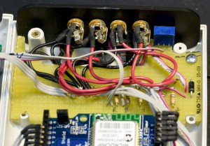
The rough schematics for the thermistors, selection button, reset button, LCD contrast adjustment, and solid-state relay output are shown below.

The code to run the Arduino is provided here. It relies on the WiShield library that was originally designed for the AsyncLabs WiShield Arduino WiFi shield, but the library also works with the LinkSprite CuHead WiFi shield. The LCD can be set up as shown in this Adafruit tutorial, although I use different pins on the Arduino than those shown in the tutorial.
The enclosure houses two buttons, one for restarting the Arduino, and the other for selecting the temperature range options and enabling WiFi during initial power up. There is also a 3.5mm jack that I use to send the digital output signal to my solid state relay that lives in a separate 2-gang electrical box alongside the 120V mains power hookup for the electric smoker.
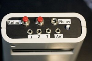
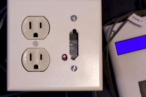
During startup, I can choose the upper and lower temperature limits for the air temperature in the smoker. When the temperature exceed the upper limit, the Arduino shuts off the solid state relay, cutting power to the electric heating element in the bottom of the smoker. As the air temperature drops below the lower temperature limit, the Arduino powers the relay up again. The temperatures for the 4 probes are reported on the LCD screen, and pointing a web browser to the WiFi shield’s IP address produces a very simple web page with the current temperatures and run time.