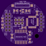
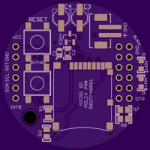
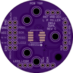
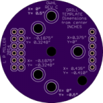
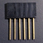
The Open Wave Height Logger (OWHL) project has reached another minor milestone with the release of a new hardware revision, RevC.
This is a redesign of the three printed circuit boards, breaking physical compatibility with the older revisions, but it maintains software compatibility with the existing OWHL code (hardware designs and code available at the GitHub repository: https://github.com/millerlp/OWHL). The goal was to make the hardware a bit easier to assemble, and make certain parts (the micro SD card) easier to reach. All of the tiny surface mount components, save a few, are now on a single side of each board, which makes it easier to use a toaster oven to do reflow soldering (the video below shows the new steps).
Here’s the list of changes:
- I removed the footprint for the 32.768kHz crystal that was on revision B. This was an experiment that didn’t bear fruit, so it no longer needs to be on the board. The system is timed via the 32.768kHz signal from the real time clock chip.
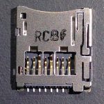 The microSD card now resides on the bottom surface of the bottom PCB board (referred to as the power board). This should make it easier to reach in certain housing designs. The microSD card slot has also been changed to a different part, Molex part number 5027740891, which is easier to hand-solder and to check, since the pins are all exposed on the back of the housing instead of hidden under the metal housing.
 The extra JST battery connectors on the power board have been removed to make room for the microSD card. A single JST PH-series connector remains for connecting the battery.
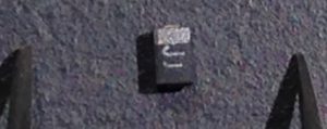 A 22uF tantalum capacitor has been added near the microSD card to make sure it has sufficient power when it wakes up. This didn’t appear to a be a problem in the previous hardware revision, but this should ensure that it doesn’t become a problem. Note that the tantalum capacitor is polarized, meaning you need to put the end with the white stripe on the + positive pad on the board.
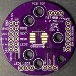 The sensor board (MS5803 board) has been altered to add an additional triangular hole pattern, alongside the original 2-hole pattern. This should help stabilize the board in designs where the sensor is mounted to a bulkhead with screws. Ultimately it may make more sense to pot the sensor to a bulkhead with epoxy since there aren’t any serviceable parts on the sensor board, rather than using the screw mounting. If you kill the $35 MS5803 for some reason, you might as well replace the whole sensor board since it just has one little capacitor and some 6-pin headers on it.
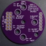 I have also created an extra template board that can be produced by the circuit board fab house that has the mounting hole layout on it. If you were hand-drilling mounting holes, this board could come in handy for laying out your hole pattern. It is completely optional and won’t be necessary for some folks.
If you want to order copies of the circuit boards, they are available as shared projects at OshPark.com:
The first versions of revision C hardware were deployed in the field during Summer 2016.

