If you’re like me, you’ve run into this problem at least once in your life (this is for about 8 people in the world total) – you deployed a Tidbit temperature data logger in the field, came back weeks or months later, and the two communications LEDs on the face of the Tidbit have been broken off by a rock.
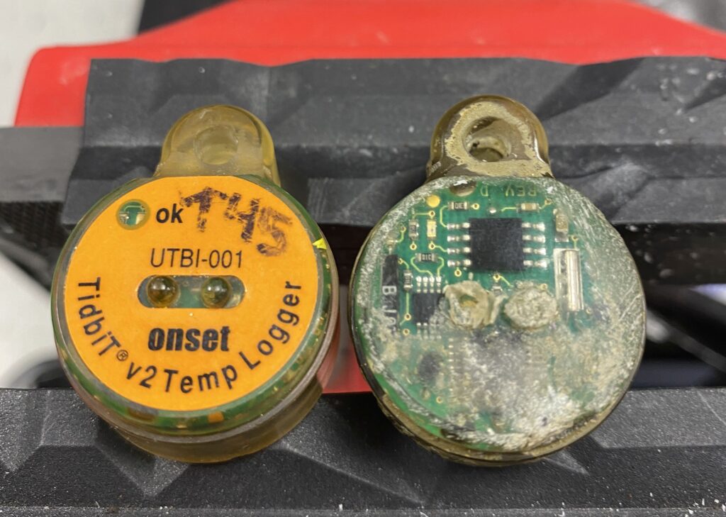
With the communications LEDs broken off, there’s no way to talk to the Tidbit even if it’s still blinking its separate status LED (next to the “ok” label) to indicate it’s alive. Well, almost no way…
Since the broken Tidbit was destined for the trash bin, I decided to see if I could de-encapsulate it enough to replace the LEDs (more correctly, it’s a LED and a photodiode that resembles a LED) and maybe talk to it one last time. Years ago I had successfully opened up a Tidbit with a dead battery and managed to power it up long enough to offload it, so this wasn’t a complete shot in the dark.
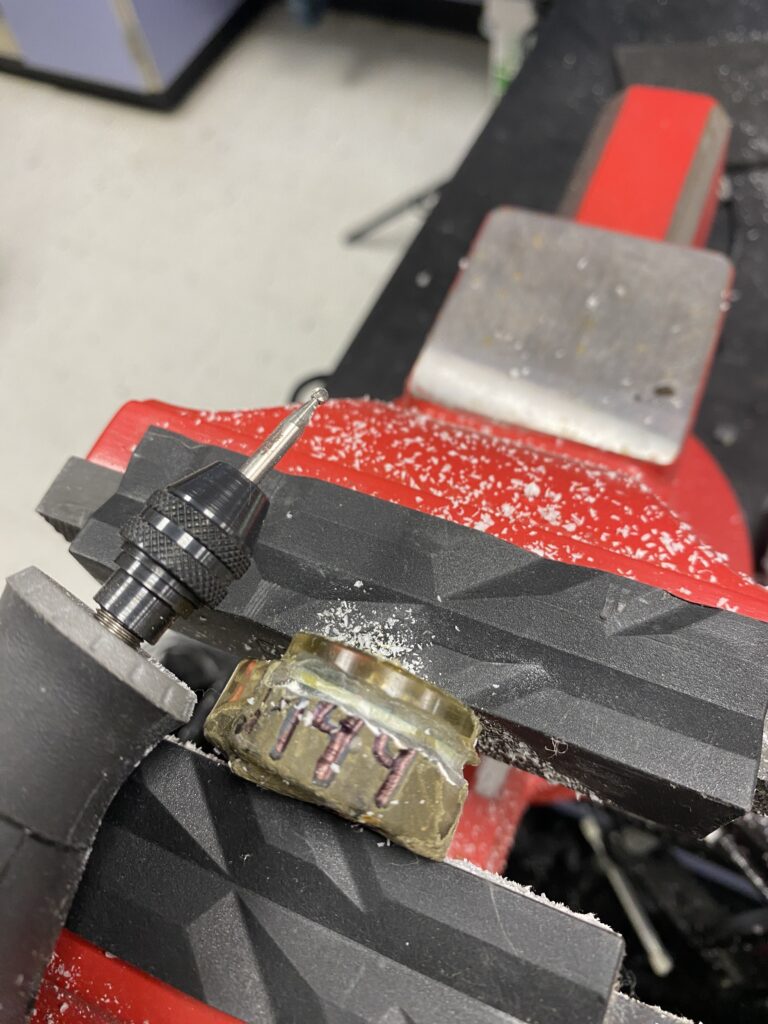
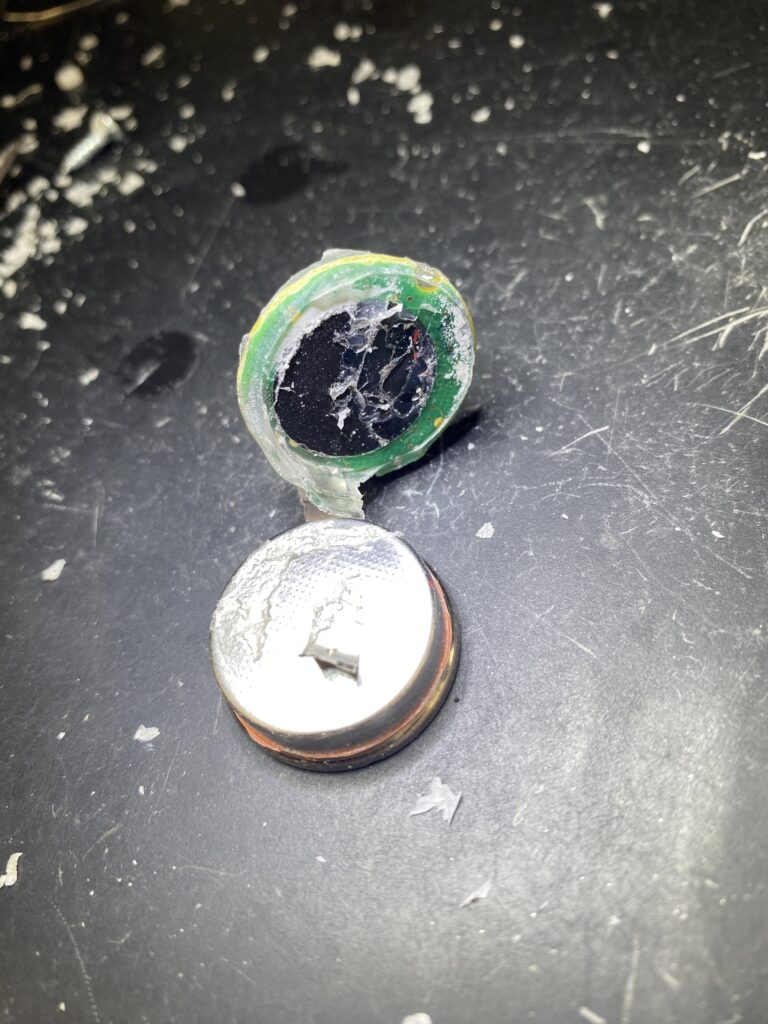
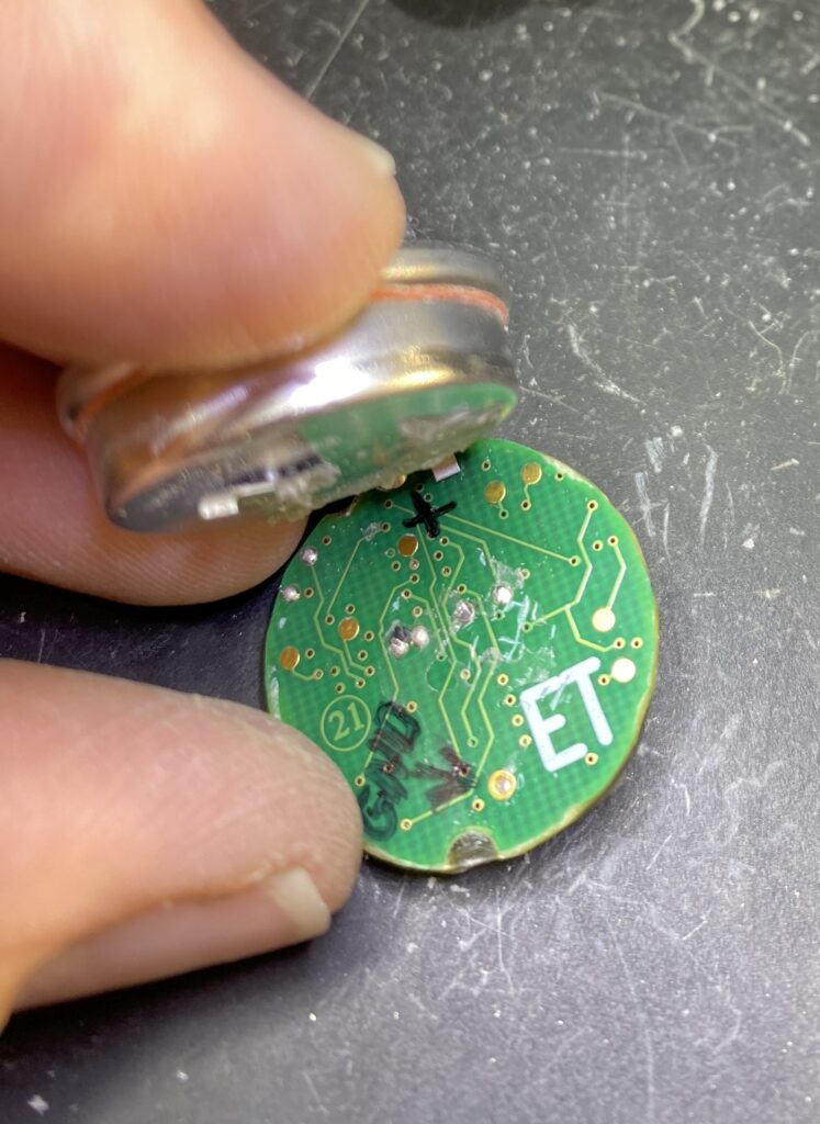
The Tidbit is completely encased in an epoxy of some sort, so you have to grind away at it to reveal the battery and circuit board. I worked my way around the circumference where the battery meets the circuit board, and got it to the point where I could pry the battery away from the board.
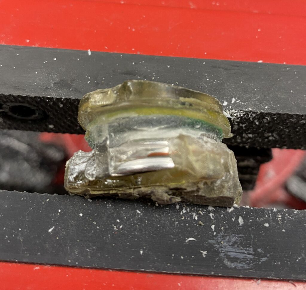
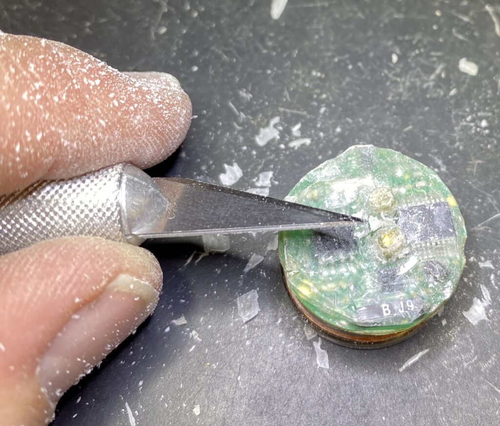
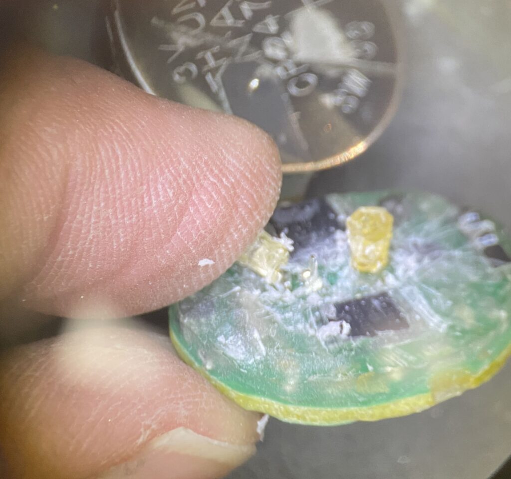
I also spent a bunch of time carefully grinding away the top surface of the Tidbit around the broken LEDs, since they would need to come out via that top side after being unsoldered from the bottom side.
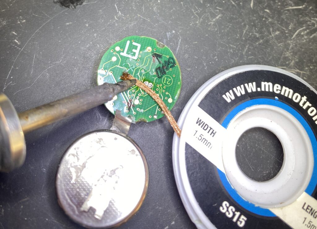
Once I was far enough along on the top side, I used desoldering braid to wick up the solder from the underside of the board where the LED and photodiode attach.
After removing the original LED and photodiode, I was left with holes designed to hold small T1 (3mm) LEDs, but they also would fit a typical T1-3/4 (5mm) sized LED body if you forced them in.
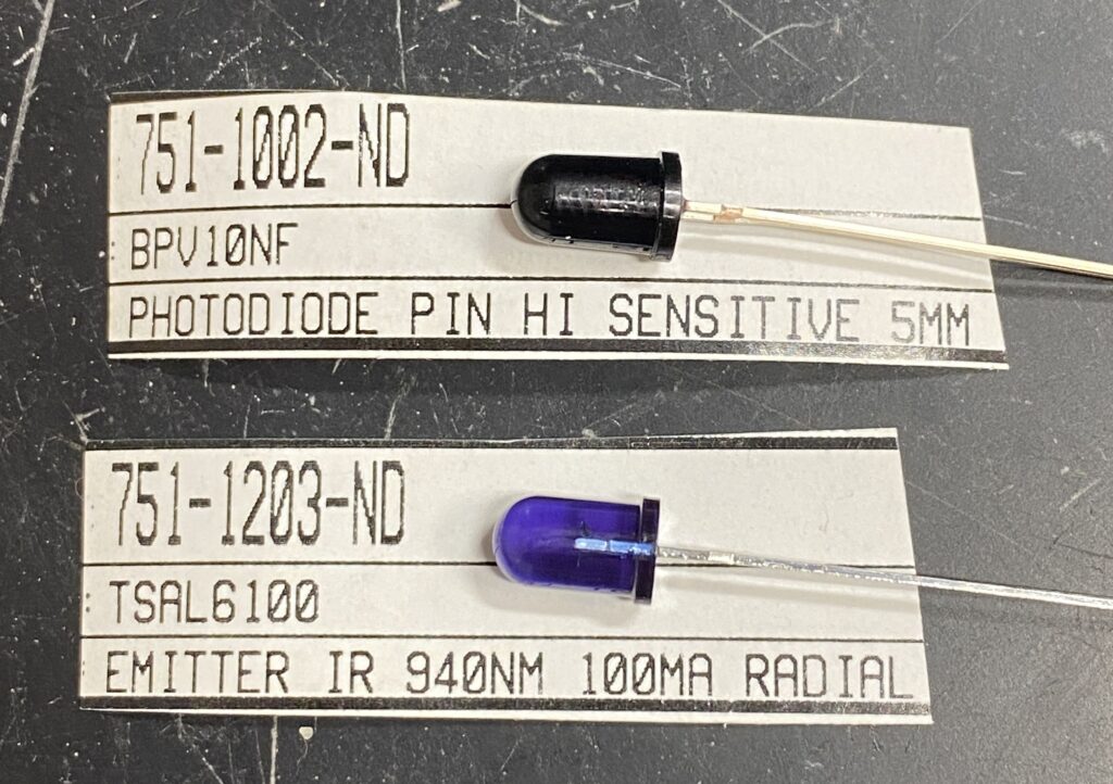
You may ask why I chose these particular parts for the replacement, and the answer is because I had them laying round. I have no idea what the specs are on the original Tidbit IR LED and photodiode, but the good news is that these new pieces worked well enough for one download.
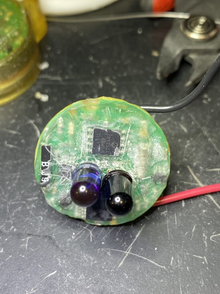
I soldered the new IR LED and IR photodiode into place and soldered on some wire leads to reattach the original battery since it still had enough juice to run this device.
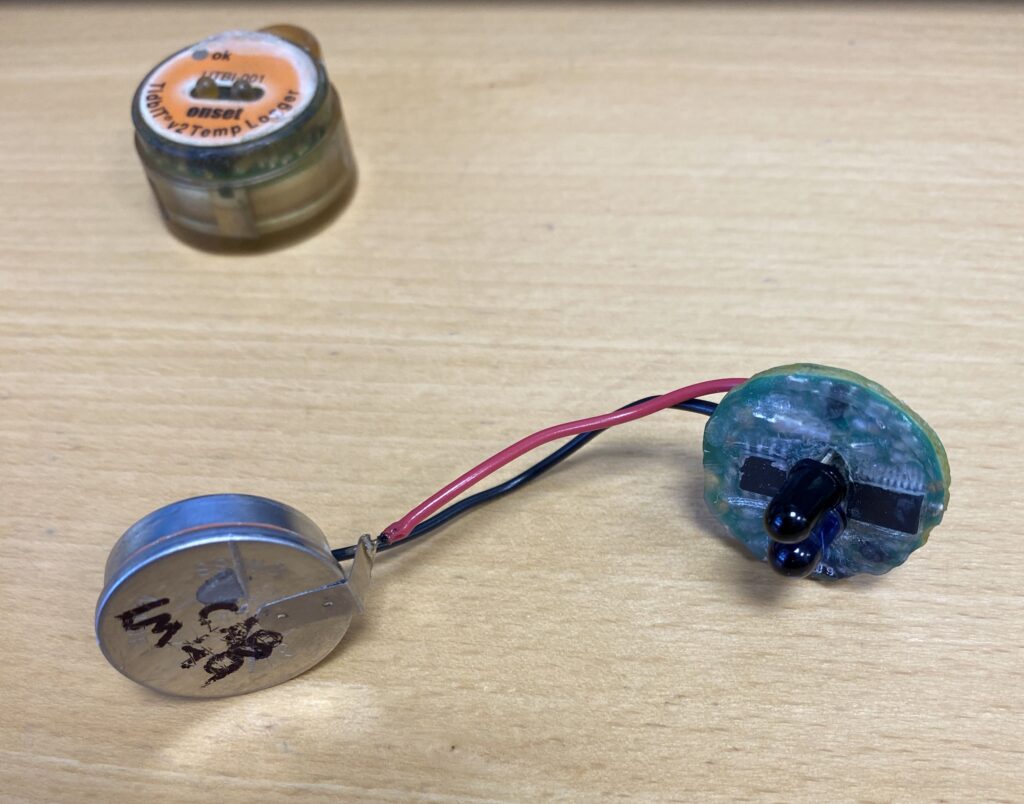
With the Tidbit powered back up (the red status LED flashed a few times), I attempted to read it with my Onset USB Shuttle.
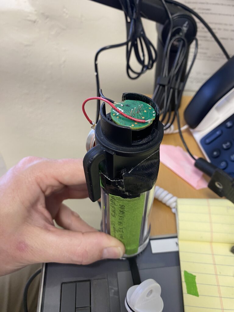
It took a lot of trial and error to find a good position where the USB Shuttle actually recognized the Tidbit. The shuttle works by pressing that black arm on the left of the picture above, and it will flash a red LED if it can’t find a Tidbit, but if you have success the shuttle will show a green LED on full time once connected. I managed to eventually get a connection, and was able to download the data via the Onset Hoboware Pro software. The Tidbit showed up with its serial number just like a fully functioning Tidbit. Initially I got a warning from the software that the Tidbit’s battery had been reset (yep), but it was willing to download like normal.
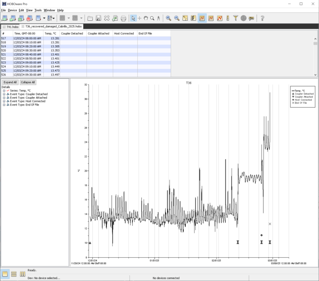
In the end I salvaged about 3 months of field temperature data. We use replicate temperature loggers placed in similar microhabitats at our sites in case we lose one, so ultimately rescuing this Tidbit just gave us the bonus of having our replication number back up to the original target, but this was also a useful proof of concept to show that the repair could be done. Now the Tidbit goes into the big pile of broken electronics that will eventually overtake my lab space.
For whatever it’s worth, if you attempt this with your own busted Tidbits, and your Tidbit’s battery is also dead, you can use most any 3 volt lithium battery, or could likely use a typical 3.3V power supply to temporarily power the resurrected Tidbit.