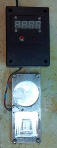
Here’s a little project that uses an ATtiny84 microcontroller, programmed with the Arduino software, to build a thermostatically-controlled heater. It allows the user to choose a temperature setpoint, and then displays the current temperature using an Adafruit 4-digit 7-segment LED display over I2C. The youtube video below demonstrates part of the project, where an ATtiny84 processor is used to drive the Adafruit display.
To get the project rolling, I installed the ATtiny core files available from High-Low Tech. The instructions there helped get the ATtiny84 running on a breadboard. I use an AVRISP mkII programmer to upload programs to the ATtiny84. One minor detail that held me up for a while initially is that you must hold down the Shift key when clicking on the Arduino Upload button if you want to upload using an external programmer like the AVRISP mkII (as opposed to uploading over a USB COM port like regular Arduinos use).
The 2nd task was to get the ATtiny to talk to the Adafruit 7-segment LED backpack. Adafruit provides a library to interface their I2C LED backpack with regular ATMEGA-based Arduinos like the Uno. Unfortunately this doesn’t work with the ATtiny chips, since they need a different I2C library to communicate. I used the TinyWireM library, which can be found in at least two flavors. The original version can be found at the Arduino.cc playground, but while this version supports the ATtiny85 (8 total pins), it lacks support for the ATtiny84 (14 pins). Scenelight.nl provides a slightly modified TinyWireM library that adds in support for the ATtiny24/44/84 family of chips.
With the ability to transmit using the I2C protocol, the 3rd task was to simplify printing values to the Adafruit LED backpack. To accomplish this, I used the Adafruit_LEDBackpack library as a jumping-off point to make a simplified library for the ATtiny chips. I’ve removed all the graphical facilities found in the Adafruit library, since they aren’t necessary for the 7-segment display. It also references the TinyWireM library instead of the original Wire library. My modified Tiny_LEDBackpack library can be found at this GitHub page, and it includes an example sketch called SevenSegTest_tiny.ino. This should work with the ATtiny84 and ATtiny85, provided you hook the SDA and SCL lines up correctly to the processor.
Once you have the TinyWireM library and Tiny_LEDBackpack libraries downloaded, they can be installed in the arduino-1.0.1/libraries directory alongside all of the other built-in Arduino libraries. Restart the Arduino software, and they should be available. The SevenSegTest_tiny.ino example sketch should be found under the File>Examples>Tiny_LEDBackpack menu.
The image below shows how to hook up the Adafruit 7-segment display and the ATtiny84 on a breadboard. I also add in a regular LED attached to pin 2 of the ATtiny to indicate when the sketch is running, even if the 7-segment display is malfunctioning. It’s also recommended to have a pair of 4700-ohm (or 10k ohm) resistors wired between the SDA and SCL lines and +5V to act as pull-ups.

There is currently an issue with the stock Arduino 1.0.1 distribution, where compiling sketches larger than 4KB for an ATtiny processor generates a “PCREL” error. This will probably include the SevenSegTest_tiny.ino example sketch provided in the Tiny_LEDBackpack library, which compiles at 4,084 bytes on my computer. Tom Carpenter provides a fix here:
http://arduino.cc/forum/index.php/topic,116674.msg878023.html#msg878023
With the display working, the remainder of the project was straightforward. My goal was to use a TMP36 temperature-sensing IC to measure the temperature of an aluminum plate. This sensor is read using the analog-to-digital converter of the ATtiny84. The aluminum plate has a 120VAC 15 watt heating pad mounted to the underside. The heating pad is controlled by an optically isolated solid state relay that can be driven directly from an ATtiny digital output pin. The solid state relay switches the heating pad on and off as necessary, and makes use of the Arduino PID library to regulate the temperature close to the setpoint. The temperature is displayed on the Adafruit display. A button allows the user to choose the temperature setpoint.


The full code for the heater is found in this GitHub repository. The basic breadboard circuit is shown below.
