Updated with new Arduino code July 8 2012.
It never hurts to collect more data, and I often find myself wanting to record temperatures from a few extra animals. Most (all?) commercial thermocouple dataloggers that will record temperatures from multiple thermocouples cost several hundred or thousands of dollars. I set out to put together a relatively cheap 8-channel thermocouple datalogger based on the open-source Arduino development platform.

By way of introduction, the Arduino development platform consists of a cheap and fairly easy-to-understand microcontroller board and associated software to easily program the microcontroller. A basic Arduino “Duemilanove” board with an Atmega328 microcontroller can be purchased for roughly $30 (AdaFruit Industries, SparkFun Electronics). The software to program the microcontroller is freely available from many sources, including the main Arduino site.
My datalogger setup consists of the Arduino board:

A SD card and real time clock shield from Adafruit Industries:

My homemade pcb to interface with the thermocouples and provide a LCD screen readout:

The LCD+thermocouple board is designed to sit on top of the Adafruit datalogger shield, which is designed to sit on top of the Arduino board. The datalogger shield uses its factory pins for the SD card and real time clock, along with the stock code base, except for the two indicator LEDS. The indicator LEDs should be unhooked from whatever Arduino pins you connected them to. The LCD+thermocouple board requires all of the remaining pins on the board, and the SD write indication is instead accomplished with the LCD. The only other modification to the Adafruit datalogger shield was the installation of female header pins with long leads (available from Adafruit, listed below) instead of the normal male header pins that it comes with. The LCD+thermocouple board uses modified male header pins to interface into the female pins of the Adafruit board.

Here’s a rough parts list and cost breakdown:
| Item | Supplier | Part # | Quantity | Cost | Total |
|---|---|---|---|---|---|
| Arduino Duemilanove | Adafruit | 50 | 1 | $30 | $30 |
| Datalogger Shield | Adafruit | 243 | 1 | $19.50 | $19.50 |
| LCD 20×4 Display | Adafruit | 198 | 1 | $18.00 | $18.00 |
| Battery pack, 6xAA | Adadruit | 248 | 1 | $5.00 | $5.00 |
| Stacking header pins, female | Adafruit | 85 | 1 | $1.50 | $1.50 |
| Header pins, male | SparkFun | PRT-00116 | 1 | $2.50 | $2.50 |
| Push button | SparkFun | COM-00097 | 2 | $0.35 | $0.70 |
| AD595 amplifier | Digikey | AD595AQ-ND | 1 | $12.35 | $12.35 |
| ADG407 multiplexer | Digikey | ADG407BNZ-ND | 1 | $9.56 | $9.56 |
| P2N2222A NPN transistor | Digikey | P2N2222AGOS-ND | 1 | $0.53 | $0.53 |
| 680 ohm resistor | Digikey | CF18JT680RCT-ND | 1 | $0.09 | $0.09 |
| 10k ohm resistor | Digikey | CF18JT10K0CT-ND | 1 | $0.09 | $0.09 |
| Trim pot, 5k ohm | Digikey | 490-3002-ND | 1 | $1.38 | $1.38 |
| 28-pin DIP socket | Digikey | 3M5469-ND | 1 | $0.27 | $0.27 |
| 14-pin DIP socket | Digikey | 3M5462-ND | 1 | $0.18 | $0.18 |
| Thermocouple jack, type-T | Omega Eng. | PCC-SMP-V-T-5 | 2 | $19.00 | $38.00 |
| Thermocouple wire (50′) type-T | Omega Eng. | TT-T-30-SLE-50 | 1 | $43.00 | $43.00 |
| Thermocouple plugs type-T | Omega Eng. | SMPW-T-M | 8 | $1.75 | $14.00 |
| Total | $197 |
Admittedly, $200 still isn’t super cheap, and that price doesn’t include an enclosure (I haven’t figured out a perfect housing yet), or the costs of the printed circuit board and tools. There should probably be some capacitors in this design as well, but I haven’t gotten there yet. Most of the small passive components and the NPN transistor in that list can be substituted with parts that are close in value.
The ADG407 multiplexer (datasheet) is what allows us to feed 8 different thermocouples into a single $13 AD595 thermocouple amplifier. The AD595 (datasheet) is designed to work with type K thermocouples, and type-T thermocouples are functionally identical over the 0°C to 50°C temperature range that most biological studies inhabit. Note that I list the AD595A model here, which is only spec’d from the factory to be +/- 3°C, but you’ll typically find that they’re pretty much spot-on when compared to a calibrated thermometer or other temperature measuring device. You also have the ability to calibrate your particular datalogger (which you should absolutely be doing) and make adjustments in software to suit the particular AD595 that you receive. There is a much more expensive $30 AD595C model available as well (+/- 1°C) that is manufactured to tighter tolerances at the factory, but I’m not convinced it’s necessary if you calibrate properly. Again, for a homemade project like this, designed by a person whose electrical engineering training consists of taking an electronics shop class in 9th grade (really), you should really be verifying the output temperatures yourself.
The Eagle schematic for the LCD+thermocouple board looks like this:
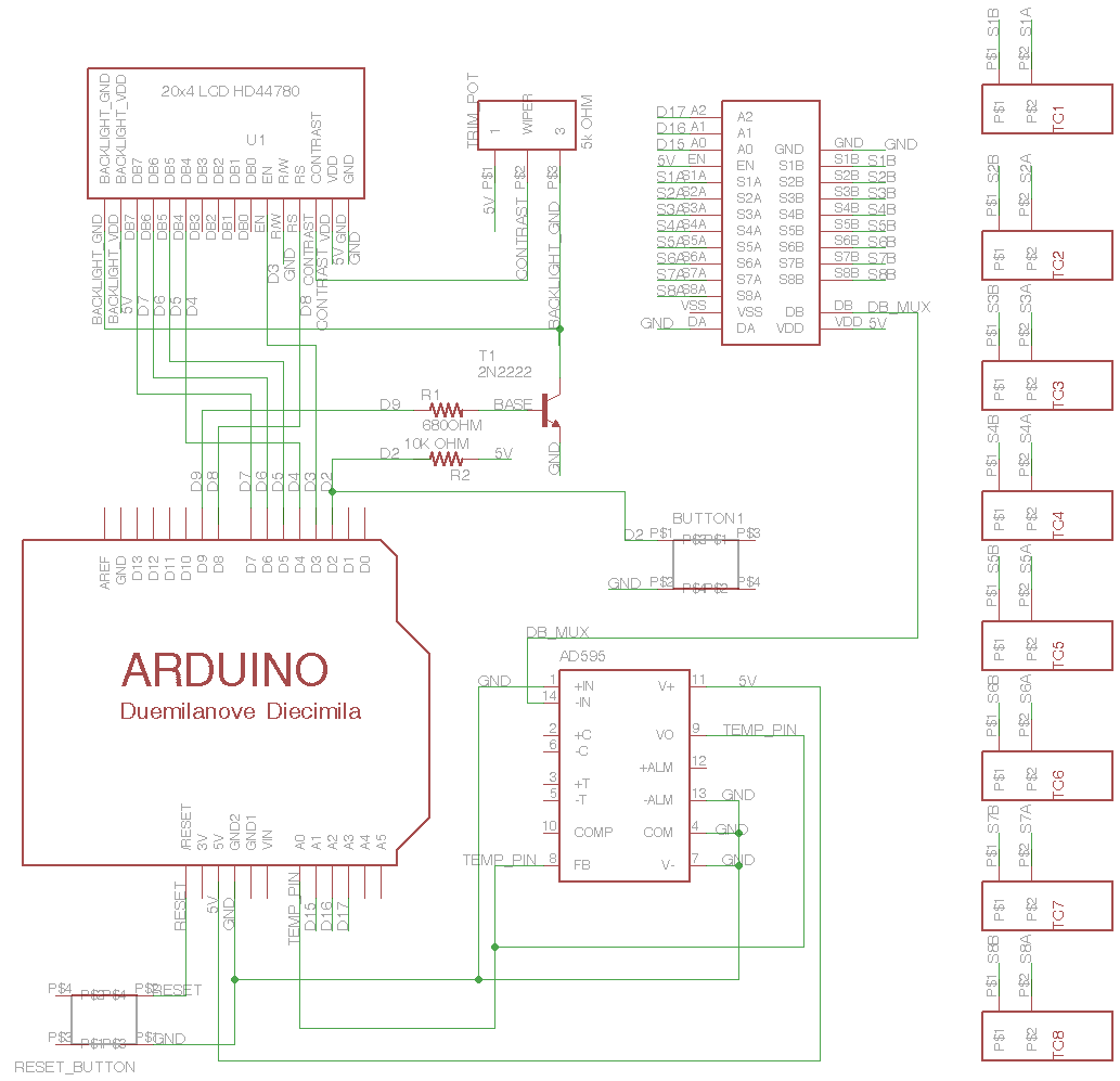
Eagle schematic file: tc_mux_board_v7.sch (updated 2013-01-31)
My layout for the LCD+thermocouple board exceeds the PCB dimensions allowed by the free version of CadSoft’s Eagle program, so I laid my board out using FreePCB, which is available as freeware. The FreePCB project file and a pdf of the bottom copper layer suitable for toner-transfer etching are available here:
FreePCB file: tc_mux_rev7.fpc
PDF of bottom copper layer: tc_mux_v7.pdf
Finally, the sketch that runs everything is here: temp_mux_proto_v7.pde (only works under Arduino v22 or earlier)
UPDATE 2012: A current version of the code, updated to work under Arduino 1.0, can be found at my github.com account:
http://github.com/millerlp/Thermocouple_datalogger
The program weighs in at 24598 bytes, which is too large to fit on an older Atmega168 microcontroller, but leaves you some room to expand on a Atmega328 or Mega.
Before running the temperature logging sketch, you must go through the initial setup routine for the Adafruit datalogger shield in order to initialize the real time clock and SD card. See the tutorial at the Adafruit site for that information.
Once everything is built and loaded, the temperature logger goes through a few initial setup screens before logging data.
First it displays the current time and date to help you verify that the timestamps will be correct.

The next screen lets the user set the data saving interval. The options range from 5 seconds to 10 minutes. The user can press a button (visible to the upper left of the LCD) to cycle through the various options. Since I’m using a 2GB SD card, it would take weeks or months to fill with the simple text data we’ll be recording, so a fast sampling rate makes sense.

Next the user is presented with the option to set how long the LCD backlight will stay on, using the same button for control. To save battery power, the LCD is shut off after some amount of time, while the datalogging routine continues running in the background. The user can hit the button any time to turn the LCD backlight on again.

After those setup steps, the datalogger begins displaying and recording temperatures from all 8 thermocouple channels. A little “save” indicator pops up after each write to the SD card.

The temp_mux_proto_v7.pde program uses a simple smoothing routine to avoid aliasing weird voltage readings. The last 10 readings on a channel are averaged and the result is displayed as the temperature for that channel. The temperature readings are occurring roughly every 500ms, and temperatures tend to change relatively slowly, so this smoothing routine won’t introduce much delay in the temperature output.
The data are written to the SD card in a comma-separated-value (.csv) file. A new file is created each time the logger is restarted, and each file gets a unique name (LOGGER00.csv, where the 00 increments each time). The data can be downloaded to any computer and opened with a spreadsheet program.

I calibrated the thermocouple temperatures against a NIST-traceable 0.1°C alcohol thermometer, with everything submerged in a well-mixed water bath. Using the thermometer as my reference, I recorded thermocouple temperatures over a range from ~0 to 50°C. For comparison, I also included a thermocouple in the water bath that was attached to a commercial Omega HH21 hand-held thermocouple thermometer.

The data for the 8 thermocouples are given in the left column, and data from the HH21 thermocouple thermometer are shown in the right column. Both sensors are reasonably linear across the full temperature range compared to the reference thermometer. My thermocouple mux transitions from reading slightly warm to slightly cool over the whole temperature range, but the majority of values are within 0.5°C of the thermometer value. Given that I was recording the thermometer values by hand and matching up the thermocouple data after the fact, the actual deviation is probably slightly less. The Omega HH21 read slightly cool across the whole temperature range, going from 0.8 to 0.2°C cooler than the thermometer as I warmed the water.
I’ve set the Arduino to use the Atmega328’s internal bandgap voltage as its analog reference voltage. The bandgap voltage is nominally 1.1V, +/- 5%. You can tweak this value in the sketch if the thermocouples are consistently reading high or low, since your Atmega chip may be slightly different from the factory. Using the bandgap reference limits the usable temperature range of the thermocouples to roughly 0-110°C, since the AD595 amplifier puts out a 10mV/°C signal that should reach 1.1V at 110°C. The bandgap voltage allows a fairly high temperature resolution, recording temperatures in 0.11°C steps. Additionally, the bandgap voltage appears to be quite stable over a range of supply voltages. I ran the logger until my battery pack dropped down to ~3.8V, so that the LCD was no longer able to light up, but the temperatures recorded by the logger were stable right up until the microcontroller quit running altogether.
The major caveat with this system currently is that it seems to be extremely susceptible to ground loop noise (see Jee Labs for a similar problem). If you use this in a noisy electrical environment, those long thermocouple wires can act as antennae and lead to wildly fluctuating input voltages and wildly inaccurate temperature values. For instance, using the heating element of my laboratory hot plate/stirrer caused all sorts of funky things to happen. Turning the heating element off (while keeping the magnetic stir bar running) let the logger record accurate temperatures. Obviously this won’t be an issue if you’re out in the field far away from any electrical noise, but usage in the lab may be hampered in some cases. The logger also picks up noise from cheap wall wart power supplies and on at least some of my computer USB ports. As a result, I run the logger primarily off of a battery pack for now.
Finally, if you’ve never put together your own thermocouples from scratch, I have an older post explaining the process: Rolling your own thermocouples