The following is a tutorial on using the freely available ImageJ program from the National Institutes of Health for estimating the area of a leaf or algae blade (or anything else). The process is straightforward once you understand the various steps.
You must begin with a photograph of your object, flattened and dried off as much as practical. Include a clearly visible ruler or other measuring device in the picture. Ideally you will photograph your dark leaf or blade on a light background to maximize the contrast between the object and the background.
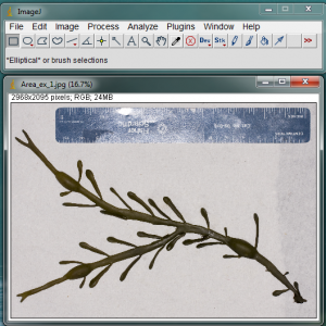
Open the image in ImageJ. In the example image above, I have included a blade of Ascophyllum nodosum and a ruler. I made a special effort to spread out the algae so that none of its parts are overlapping. I also dried it with a paper towel so that there were no highly reflective surfaces when I took the picture.
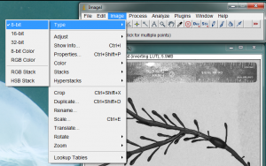
The area measurement process requires the image to be analyzed as a gray-scale 8-bit image. Convert your image to a grayscale image by going to the Image>Type>8-bit menu item.
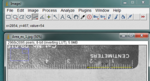
It is also necessary to give ImageJ a size reference for the objects in the image. Use the straight line tool to draw a line between two points on your ruler. In the image below, I zoomed in on the ruler and drew a line between the zero and 2cm lines on the ruler.
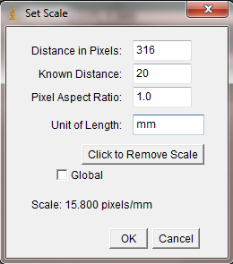
With the line drawn on the image, go to the Analyze>Set Scale… menu item.
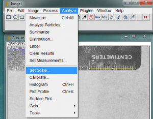
In the window that opens, enter the length of the line you drew on the ruler. In my case the line covers 20mm on the ruler. Enter this value in the Known Distance box. In the Unit of Length box, you may enter the units of measurement (millimeters in my case). The “Distance in Pixels” in the Set Scale window is the length of the line you drew (don’t change this value). Because ImageJ now knows the number of pixels that equal your known distance, it can calculate a length or area anywhere else on the image. Of course this assumes that all of your measured objects are in the same plane relative to the camera lens.
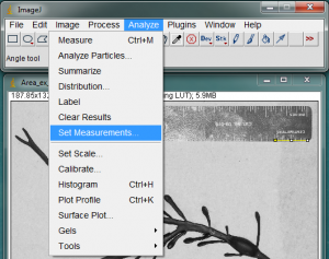
For the first picture you analyze, you may also want to select what quantities will be measured. Go to Analyze>Set Measurements… to set this.
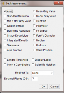
In the Set Measurements window, make sure Area is selected. All of the other options can be unchecked.
The next step is to “threshold” the image. This process is meant to turn the dark parts of the image black, and the light parts of the image white. This is necessary for the area measurement process coming up next. Begin the thresholding process by going to Image>Adjust>Threshold…
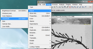
The Threshold window will pop up and portions of your original image will turn red.
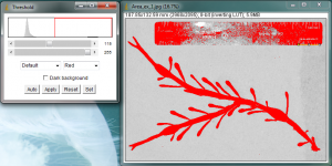
The goal here is to turn your leaf or algae blade completely red, while leaving the surrounding background not-red. All of the red areas will be turned black in the next step, and we will measure these black areas. It will be necessary to adjust the sliders on the Threshold window to control what portions of your image are turned red. Change the sliders until all of your leaf is covered in red, but do not let the surrounding background turn red. When you are satisfied, hit “Apply” in the Threshold window. I purposely did a poor job adjusting the threshold limits in my image in order to leave some white specks inside the blade, so that I can show how to deal with these areas later.
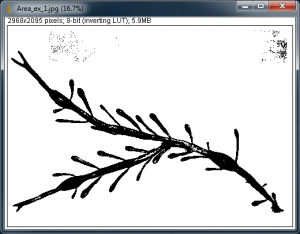
Next select the Wand tool from the ImageJ tool bar, and click on the black of the algae blade. It will be outlined in yellow. The yellow outline shows the outer edge that will be used in the area calculation.
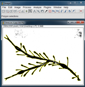
With the algae blade silhouette selected, go to Analyze>Analyze Particles… to open the Analyze Particles window.
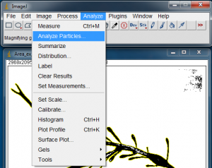
In the Analyze Particles window you are given several options. The Size box lets you set the upper and lower size bounds of objects to be measured. If you have selected your blade or leaf with the Wand tool, it will not be necessary to alter this box. Set the Show menu to “Masks”, so that the resulting measured area will be displayed for your later perusal. You can also decide whether to include “holes” (white spots) inside the selected object as part of the measurement. If your leaf or blade has many little white specks that couldn’t be eliminated during the threshold process, you could select “Include Holes” to simply treat those speckles as part of the leaf area. However, if your leaf or blade has real holes in it that you don’t want measured, uncheck this box.
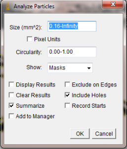
When you hit “Ok” in the Analyze Particles window, ImageJ will quickly measure the area of your selected black blob. It will open a new window showing the “mask”, which is just a representation of the area included in the area calculation. In the following two pictures, I show the effect of using the “Include Holes” option on my poorly thresholded algae blade. In the first mask shown below, I told ImageJ to not include the white specks in the area calculation. The resulting mask has the white holes left in to show that they were not counted. The second mask below was done with the “Include Holes” box checked, so that the white spots on the blade would be included in the area calculation. As a result, the white holes do not appear in the 2nd mask, since they were included in the area.
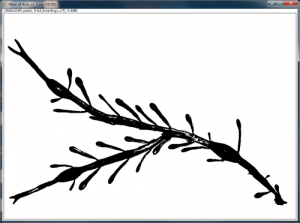
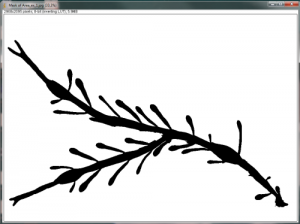
When you carry out the Analyze Particles routine, a Summary window will also pop up. This will show the total area (in your units).
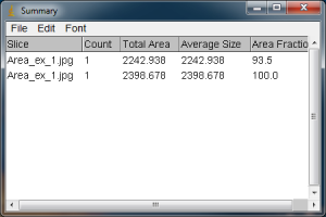
As expected, when you use “Include Holes”, the resulting area is larger if you had any white specks inside the yellow outline of your selected black blob. It is important to look at the yellow outline of your blade or leaf to make sure that everything you want highlighted is actually highlighted, and that there aren’t any unexpected holes being enclosed. The results of the Analyze Particles area calculation are given in the units I entered earlier in the Set Scale window. If I do not include the white holes in my blade, the calculated area is 2242.938 mm squared, whereas if I do include the holes in the blade (because they were just reflections of light, not true holes), the area is larger, 2398.678 mm squared.
If your original images prove troublesome during the thresholding steps due to reflections or uneven background darkness, you can manually go over the image with the paint brush tool to change areas to dark or light colors. In some cases you may want to use a white paintbrush to erase portions of the background that are close to the same color as your leaf or blade. In other cases you may want to manually fill in light spots on the leaf or blade with a black color so that it is all counted during the area measurement. The eye dropper tool can be used to select colors for painting, either by clicking on a color in your image, or by double-clicking on the eye dropper tool and selecting a color from the window that pops up. The size of the paintbrush can be altered by double-clicking on the paintbrush tool. Try doing your painting on the grayscale image before you do the threshold step, so that you can tell what should be included and what should be excluded in the picture.
It is also worth pointing out that if your thresholded images are clean and uniform, with no holes in them, you can skip the “Analyze Particles” step and simply click on a the silhouette, then press Ctrl+M to produce an area measurement of the blob. The resulting measurement will appear in a Results window. This could save you lots of time if you have multiple blobs in the image to measure and they’re all uniformly black after thresholding.